Laser Vibration Measurement Systems: LDV Principles and Selection

Measure vibration without contact

Laser Doppler vibrometry turns reflected laser light into a surface-velocity record for modal testing, NVH and structural monitoring. Ommatidia’s parallel Laser RADAR captures vibration at multiple points together and connects the response with measured geometry.

The Doppler principle

The Doppler effect is the change in frequency observed when a wave source moves relative to the observer. An approaching ambulance sounds higher in pitch; as it moves away, the pitch falls. LDV applies this frequency-shift principle to reflected laser light to measure surface motion.

The Man who Discovered the Doppler Effect
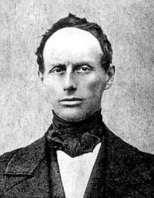
Portrait of Christian Doppler, the physicist associated with the Doppler effect
Christian Doppler, whose work explains the frequency shift used in LDV

An Austrian physicist, Christian Doppler, first described how wave frequency changes with relative motion. In 1842, his work laid the foundation for modern tools that interpret motion by analyzing frequency shifts, including radar, astronomy, medical ultrasound, and laser Doppler vibrometry.

Ommatidia’s Q1 and Q2 Laser RADAR systems combine parallel vibration acquisition with measured 3D geometry. Synchronized measurement points help engineers examine automotive parts, structural response and industrial machinery, bringing location and motion into the same analysis.

Choose a system for the measurement you need

A laser vibration measurement system records dynamic surface motion without an attached sensor. Laser Doppler vibrometry (LDV) converts the Doppler shift in reflected light into line-of-sight surface velocity. Integrating that velocity record provides displacement data for vibration analysis.

System typeBest fitMeasurement patternPlanning focus
Single-point LDVOne location or a small set of targeted measurementsOne point at a timeFocused measurement at the selected location
Scanning LDVMode shapes and spatial vibration maps under repeatable conditionsPoints measured sequentiallyStable response across the sequential scan
Parallel Laser RADARTransient or distributed response where simultaneous capture and geometry are usefulMultiple optical channels at onceClear optical path, target return and application-matched configuration
Accelerometers or a hybrid testContact references and embedded monitoringPhysical sensors at selected locationsInstallation, cabling and sensor-mass planning

For parallel vibration capture, Ommatidia Q2 provides 65 simultaneous channels and supports up to 1,300 measurement points with 20× oversampling. Q1, Q1S and Q2 measure vibration velocity to ±155 mm/s. Start with the target, working distance, motion bandwidth and spatial coverage to define the acquisition and analysis workflow.

Compare LiDAR, RADAR and Laser RADAR

Further reading

Rothberg et al. (2017), An international review of laser Doppler vibrometry, explains the measurement principle, scanning methods and practical optical effects such as laser speckle. These methods connect reflected light with surface-velocity data for vibration analysis.

Technical review. Reviewed by Eduardo Margallo, Ommatidia, on 8 August 2026.

The Doppler Effect: A Primer

Measure the response without attached sensors

Laser Doppler vibrometry acquires vibration data optically, preserving the test article’s mechanical response without added sensor mass or measurement cables. Engineers use this approach on lightweight structures, small components, thin panels, hot surfaces and moving parts.

The surface-velocity record supports automotive NVH, aerospace testing and microstructure characterization.

Using Light to Measure Movement

To measure vibration, the Doppler effect is applied using a focused laser beam. When a surface moves—whether it oscillates, rotates, or shifts—the frequency of the reflected laser light changes slightly compared to the original beam.

This slight change in frequency is called a Doppler shift.

This tiny frequency shift reveals important details about the surface’s velocity and displacement. By analyzing these changes, engineers gain precise insights into how the surface vibrates — often down to nanometer-scale motion.

Fundamentals of Laser Doppler Vibrometry (LDV)

Using the Doppler effect, Laser Doppler Vibrometry (LDV) measures surface vibrations remotely, capturing frequency shifts in reflected laser light for accurate and rapid vibration measurement and assessment.

Schematic of a basic Laser Doppler Vibrometer
Schematic of a Basic Laser Doppler Vibrometer

01 Coherent Laser Beam Emission

A stable laser beam targets the surface being tested, such as a rotating machine part or a car body panel during noise and vibration tests.

02 Frequency Shift & Doppler Detection

As the surface moves, the reflected laser light experiences a frequency shift that corresponds to its velocity.

03 Signal Processing

The system processes the frequency shift into velocity data and integrates it over time to calculate relative displacement.

04 Real-Time Output

LDV delivers real-time data on amplitude, phase, and frequency while scanning systems build a vibration map across multiple points.

When LDV fundamentals become a measurement-workflow decision

Connect the LDV measurement principle to your test campaign. Target size, working distance, coverage and simultaneous acquisition define the workflow. Compare scanning LDV with Ommatidia’s Q-Series Laser RADAR systems to select the geometry and vibration data your application needs.

Compare workflows

Laser RADAR vs scanning LDV for non-contact vibration measurement decisions.

Automotive NVH

Review the full-field vibration workflow for body, panel, and modal testing.

Bridge monitoring

Move from LDV basics to bridge vibration, deflection, and civil SHM workflows.

Q2 product fit

Evaluate denser dynamic characterization with integrated metrology and vibrometry.

The Doppler Effect in Modern Applications of Laser Vibrometry

Testing for noise and vibration is essential for maintenance and safety in numerous industries and applications. Laser Doppler vibrometry measures vibrations without touching the object, using the Doppler effect to capture precise data on movement and velocity in real-time. Engineers then use this data to calculate relative displacements, a key factor in ensuring equipment performs reliably.

Modern scanning laser vibrometers take this concept further. They combine the precision of the Doppler effect with advanced scanning technologies to map vibrations across large surfaces quickly and without contact. These tools have become vital in applications like structural health monitoring, industrial diagnostics, and automotive vibration testing.

Video demonstrating precise, non-contact floor vibration measurement with Ommatidia’s Q1 Laser Radar.

Comparison of accelerometer and laser Doppler vibrometer measurements

Comparison between accelerometer and laser Doppler vibrometer

Side-by-side bridge vibration data comparing Q1S laser Doppler vibrometer and accelerometer signals
Bridge Velocity Data from Q1S vs. Accelerometer Signal: A Side-by-Side Vibration Analysis

Benefits of Laser Doppler Vibrometry

Surface velocity connects vibration frequency, amplitude and structural response.

In practice, the velocity trace is the starting point for several engineering decisions: peak amplitudes show where motion is concentrated, frequency content reveals resonances, and integrated displacement helps teams compare dynamic behavior against design limits.

Because the measurement is optical and remote, engineers can test bridges, rotating equipment, vehicle panels, or delicate assemblies without adding sensor mass or changing the vibration response.

01 Non-Contact Measurement

Optical acquisition records surface motion from a stand-off position, with no attached sensor mass or measurement cables on the test article.

02 High Accuracy and Detail

LDV uses the Doppler effect to detect small changes in velocity. As a result, it provides precise data for tasks like balancing rotating shafts or checking stability on assembly lines.

03 Wide Frequency Range

LDVs measure a wide range of vibrations. For example, they can capture low-frequency movements in large structures or high-frequency vibrations in fast-moving motors and turbines.

04 Fast and Flexible

Scanning LDV builds spatial vibration maps across successive measurement positions. Parallel Laser RADAR acquires multiple points together for distributed and transient response.

Plan a clear LDV measurement

Six practical inputs connect the optical setup with useful vibration data.

Define the measurement locations, surface return and vibration bandwidth at the start of the campaign. These inputs guide the optical geometry, acquisition settings and choice of single-point, scanning, tracking or parallel measurement.

Record the setup and reference measurement alongside the project’s acceptance criteria so the results connect directly to the engineering decision.

Aperture diversity combines multiple optical returns to support a stable vibration record. The diagram shows how the received signal is combined before the motion data is interpreted.

Comparing single-aperture sensors with compound aperture diversity.

01 Optical access

Position the laser head with a direct view of the selected target locations. Match the working distance and beam orientation to the surface motion and spatial coverage.

02 Measurement environment

Use a stable instrument position and plan shielding or environmental control around dust, air movement and ambient light. Record the setup with the measurement data.

03 Campaign resources

Plan the instrument, setup time, sensor installation and acquisition time together. The required coverage and simultaneous point count help select the measurement architecture.

04 Sampling and filtering

Set the sampling rate, filters and acquisition duration for the vibration frequencies of interest. Keep the acquisition bandwidth aligned with the analysis output.

05 Rotating and reflective targets

Select the beam orientation, alignment, tracking and surface preparation for the target’s rotation and optical return.

06 Speckle management

Use optical alignment, surface preparation and return diversity to support signal continuity on rough, reflective or moving targets. SpeckleGuard applies aperture diversity to the received light.

Explore how SpeckleGuard technology minimizes speckle noise through optical return diversity.

For large structures and field campaigns, connect distributed vibration response with measured geometry. Compare Laser RADAR with scanning LDV to plan the capture method and coverage.

Relative bridge displacement measured from 21 metres during a train pass with Q1S
Relative Displacement of a Bridge upon a Train Passing Measured from 21m with Q1S.

Relative Displacements from Vibration Data

Integrate surface velocity to study relative displacement and dynamic response.

The velocity time history also provides a route to relative displacement. The resulting motion profiles support engineering work on structural response, machinery and vehicle components.

01 Stress and Strain Analysis

Engineers often need to know how much a part bends or flexes under pressure. This depends on displacement measurements.

02 Condition Monitoring

Radial displacement and alignment data help engineers compare rotating-machine behaviour and identify changes in operation.

03 Automotive Design

Tracking how engine mounts or body panels move during operation improves vehicle design, making rides smoother and quieter.

Relative displacement follows from integrating the velocity record over time: x(t) = ∫v(t) dt. Define the reference, integration band, filtering and drift correction as part of that analysis.

Combine the time history with frequency analysis to identify resonances, compare vibration amplitudes and study the motion of the measured structure or component.

Applications of laser Doppler vibrometry

Remote surface-velocity measurements support engineering studies across structures, vehicles, machinery, electronics and acoustics. Choose the spatial coverage and acquisition architecture for the response you want to observe.

Laser Doppler vibrometry for bridge and civil-structure vibration measurement

Structural & Civil Engineering

Bridge displacement and modal analysis
Health monitoring for buildings, towers, and large structures
Crack detection and resonance testing

Laser Doppler vibrometry for automotive and transport NVH measurement

Automotive & Transportation

NVH analysis
Brake, engine mount, powertrain, and body panel vibration studies
Tire dynamics, rotor balancing, and drivetrain diagnostics

Laser Doppler vibrometry for aerospace structural vibration testing

Aerospace & Spacecraft

Structural modes of airframes, wings, turbine blades, and composite panels
Ground vibration testing
Non-contact inspection for satellites and spacecraft components

Laser Doppler vibrometry for industrial machinery condition monitoring

Industrial Machinery & Manufacturing

Condition monitoring of rotating machines
Alignment analysis, shaft vibration, and imbalance detection
Quality assurance on production lines
Laser Doppler vibrometry for MEMS and electronics vibration testing

Microstructures & Electronics

MEMS characterization
PCB vibration testing
Hard-disk, micro-motor, and speaker diaphragm analysis

Laser Doppler vibrometry for biomedical and acoustic research

Biomedical & Acoustics Research

Middle-ear vibration studies
Acoustic material testing
Ultrasonic transducer characterization

Non-contact acquisition preserves the response of delicate components and reduces installation work on moving machinery and large structures. Geometry-linked vibration data helps locate the measured response on the test article.

Complementary vibration measurement methods

Connect each measurement method to the quantity and coverage your test needs. A hybrid campaign can combine optical vibration data with acceleration, strain, displacement or image-based measurements.

Accelerometers

Measure acceleration at the installed sensor location. Accelerometers support reference measurements, embedded monitoring and instrumented vibration tests.

Strain gauges

Measure local strain with a bonded sensor. Their installation and temperature compensation form part of the measurement setup.

High-speed cameras and digital image correlation

Use synchronized images to map surface motion and deformation. Plan the view, illumination, frame rate and image scale for the motion of interest.

Ultrasonic sensors

Use acoustic signals for distance, displacement or thickness measurements. Match the sensor arrangement and acquisition bandwidth to the target and required output.

RADAR vibrometers and microwave sensors

Use radio-frequency signals for remote range and motion measurements. Working distance, spatial coverage and the required output guide the system choice.

Contact probes and LVDTs

Measure displacement at a physical contact point. Plan the fixture, travel range and reference position for the component under test.

LDV delivers remote surface-velocity data. Combine it with the reference channels and spatial coverage that support your test objective, from a focused measurement to a distributed vibration map.

Q1 and Q2: geometry and vibration in one workflow

Ommatidia Q1 and Q2 Laser RADAR systems combine parallel optical vibration acquisition with 3D geometry. Engineers can locate the dynamic response on the measured surface and compare motion across multiple positions.

FMCW ranging and interferometric velocity measurement connect shape and motion for structural monitoring, automotive NVH and industrial machinery studies.

portable Q1 laser radar by Ommatidia mounted on a metrology tripod
Q2 Laser RADAR by Ommatidia - world's first multi-channel Laser vibrometer

Parallel optical acquisition

Q1 provides 128 parallel beams. Q2 acquires 65 channels simultaneously and supports up to 1,300 measurement points with 20× oversampling. Q1, Q1S and Q2 measure vibration velocity to ±155 mm/s.

Geometry-linked vibration data

Capture surface geometry and dynamic response in the same measurement workflow, keeping the location of each velocity record available for interpretation.

Stand-off measurement

Acquire vibration data from a remote instrument position. This reduces sensor installation work on large structures and equipment with difficult access.

Signal processing for analysis

Use the acquired velocity time histories to examine amplitudes, phase, frequency content and relative displacement in the analysis workflow.

From acquisition to engineering analysis

Connect measurement planning, vibration acquisition and data analysis in a defined workflow. Bring optical measurements together with the other channels used in the test campaign.

Automotive and industrial applications

Study NVH, component dynamics and rotating-machine response with parallel optical measurements. Relate the observed motion to the measured geometry and test conditions.

Turn vibration data into a measurement decision

LDV converts reflected laser light into a surface-velocity record. Spatial coverage and simultaneous acquisition reveal how that response varies across the measured object. Ommatidia combines these vibration data with geometry to support a clear engineering review.

Review your vibration measurement workflow with Ommatidia

Share the target, working distance, point coverage and geometry or vibration data you need. An Ommatidia engineer will help define the acquisition and analysis workflow for your application.

Laser Doppler vibrometry questions

What does laser Doppler vibrometry measure?

Laser Doppler vibrometry measures surface velocity without attaching a sensor. It converts the Doppler shift in returned light into a velocity time history for resonance, operating-deflection and modal analysis, with relative displacement derived from the same record.

Which laser vibration measurement system fits each workflow?

Single-point LDV captures focused measurements, scanning LDV builds sequential spatial maps and parallel Laser RADAR captures many points simultaneously. The right architecture connects the required coverage, acquisition time and dynamic response to the engineering result.

Where is LDV used?

LDV supports modal testing, operating-deflection-shape analysis, NVH, structural dynamics and vibration studies on light, hot, moving or hard-to-reach components. Non-contact acquisition preserves the structure while delivering dense measurement data.

How do teams select an LDV configuration?

Start with the target, working distance, motion bandwidth, velocity and displacement range, point count, simultaneous-capture needs and required output. These inputs define the optical setup, acquisition architecture and analysis workflow.