3D Velocity Field & Strain with a Single LASER RADAR

3D Vibrometry Made simple

Ommatidia Q2 reconstructs full field 3D velocity vectors from multiple views using one parallel scanning Laser RADAR. Achieve modal analysis, ODS, and strain ready outputs with a compact, deployable setup that preserves a clear evidence chain from raw data to engineering deliverables

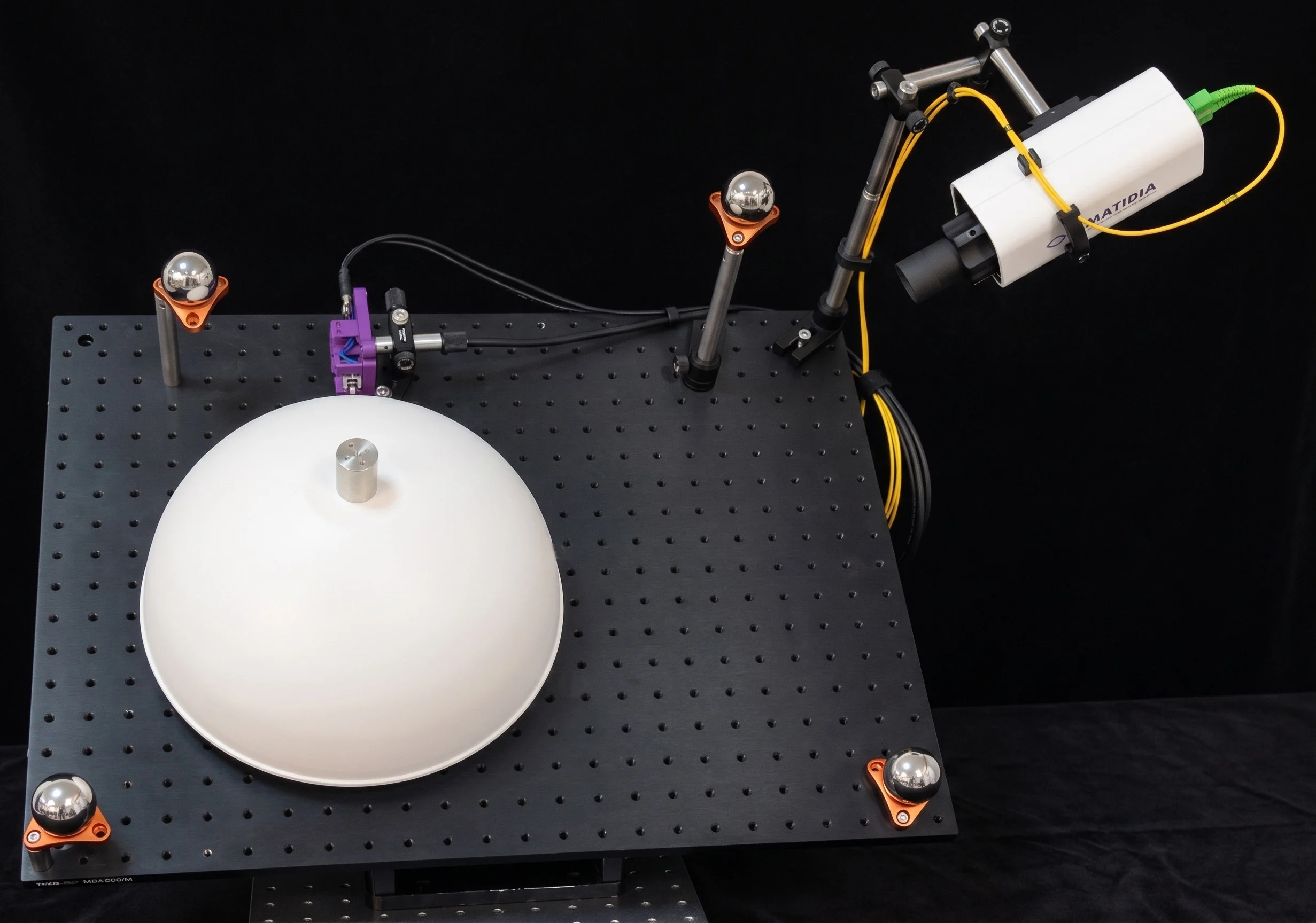
Breakthrough Ommatidia Q2 reconstructs full field 3D velocity vectors from multiple views using one parallel scanning Laser RADAR. Achieve modal analysis, ODS, and strain ready outputs with a compact, deployable setup that https://ommatidia.tech/wp-content/uploads/2026/06/mkt-1312-03.webp 18548 laboratory setup single laser radar scanning curved metal panel with spherical fiducial markers engineering test bench Breakthrough: 3D velocity field reconstruction with 1 single Laser RADAR: featured visual context.

LDV measures velocity along the beam; a single view is a projection and can misrepresent true motion on curved or complex structures. - Multi-view observations make vector components observable across shells, lightweight panels, blades, vehicle parts, civil elements, and lab test articles where motion includes out-of-plane, in-plane, and local rotations.

https://ommatidia.tech/wp-content/uploads/2026/06/mkt-1312-06.webp 18575 docx-08-image2 https://ommatidia.tech/wp-content/uploads/2026/06/mkt-1312-09.webp 18602 docx-02-image10 Key advantages

Simple: One single Q2 recovers a complete 3D velocity field.

  • Compact & affordable: Avoid multi-LDV rigs, robotic arms, and heavy lab integration.
  • Fast: No per-point calibration campaigns; the same instrument provides metrology and vibrometry.
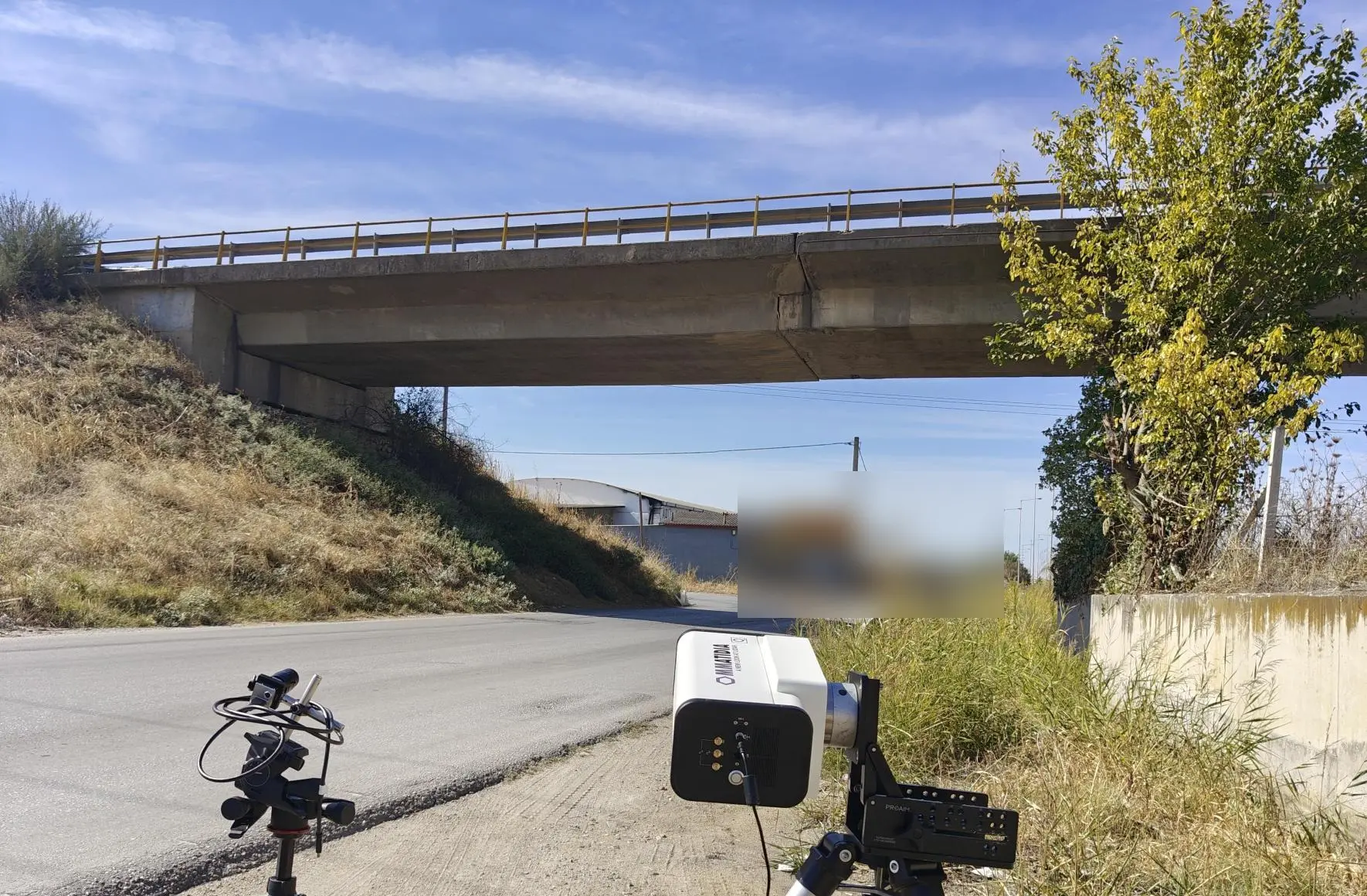
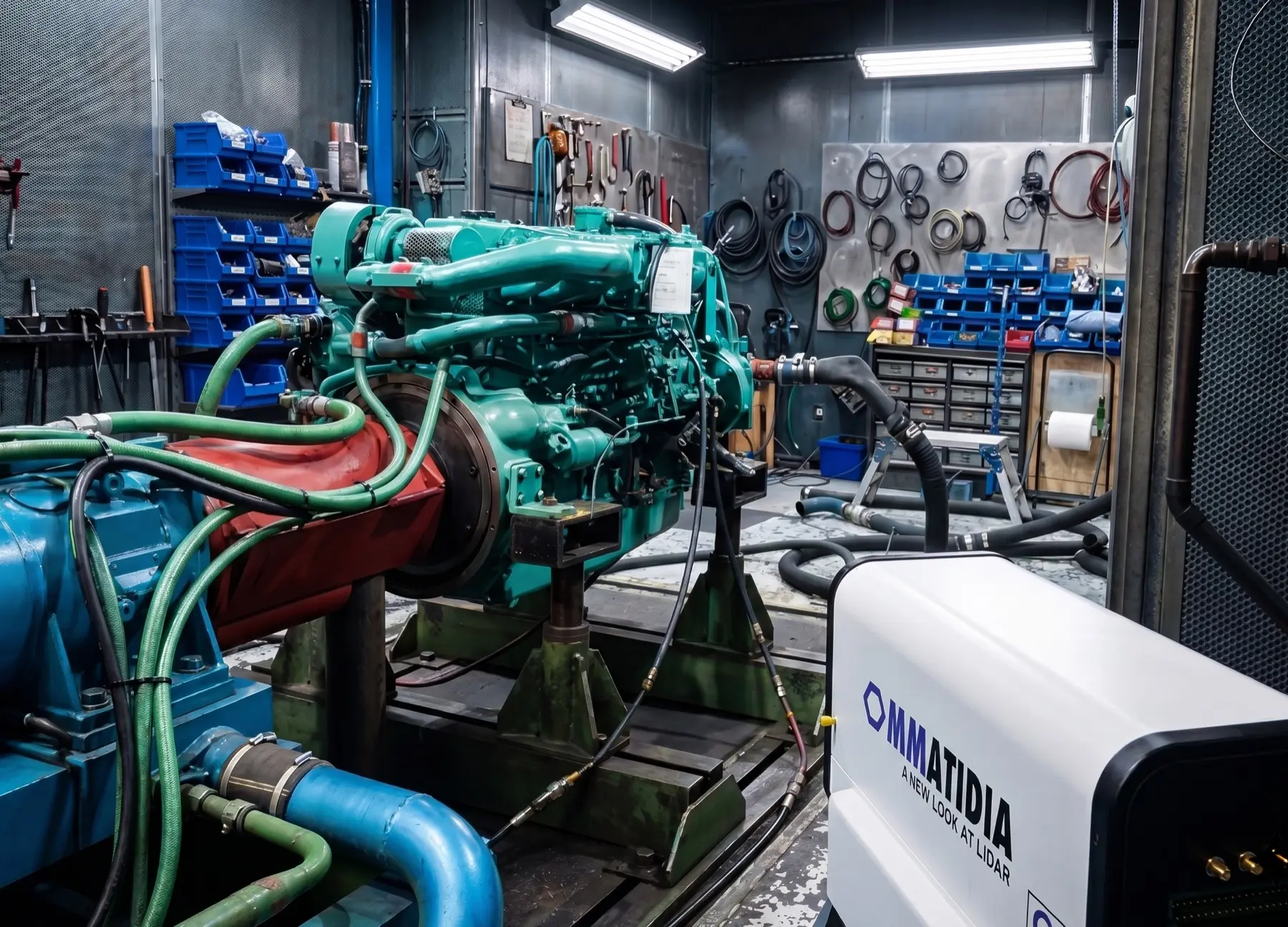
  • Versatile: Deployable in labs, factories, and field sites without dedicated installations.
https://ommatidia.tech/wp-content/uploads/2026/06/mkt-1312-09.webp 18602 docx-02-image10

Ommatidia Q2 extends Laser Doppler Vibrometry from directional, line-of-sight measurements to full-field 3D velocity vectors—using one single parallel-scanning Laser RADAR. By acquiring multiple Q2 views, registering them via spherical fiducials, and phase-aligning the data, the recovery software estimates the three velocity components at each surface point. The result is a coherent 3D motion field suitable for FEM correlation, modal analysis, ODS, and strain-ready outputs.

https://ommatidia.tech/wp-content/uploads/2026/06/mkt-1312-12.webp 18629 docx-03-image11
  • Per view, Q2 acquires a point cloud, beam directions, and line-of-sight (LoS) velocity at illuminated points. 2) For each surface point seen from three or more independent directions, the 3D velocity vector is solved from the LoS projections; extra views improve robustness via weighted least squares. 3) Local quality indicators assess observation count, residuals, and geometric conditioning. 4) Export allows advanced visualisation and further processing in commercial FEA/engineering software packages.
https://ommatidia.tech/wp-content/uploads/2026/06/mkt-1312-15.webp 18656 docx-04-image12 https://ommatidia.tech/wp-content/uploads/2026/06/mkt-1312-18.webp 18683 docx-05-image13

Plan as a single coordinated campaign, not isolated scans.

  • Use Ommatidia planner tools to evaluate spatial coverage, sampling density, geometric consistency, phase consistency, and repeatable signal quality across views.
  • Generate synthetic datasets to load in the reconstruction tool.
  • Compare agains the ground truth to assess the effect of different experimental protocols, reconstruction algorithms and conditions (sampling, noise, interpolation scheme, etc.).
https://ommatidia.tech/wp-content/uploads/2026/06/mkt-1312-18.webp 18683 docx-05-image13 Breakthrough Talk to Ommatidia

Discuss how this measurement approach could support applications workflows with the Ommatidia team.

Breakthrough: 3D velocity field reconstruction with 1 single Laser RADAR: featured visual context.

Application overview

LDV measures velocity along the beam; a single view is a projection and can misrepresent true motion on curved or complex structures.

Multi-view observations make vector components observable across shells, lightweight panels, blades, vehicle parts, civil elements, and lab test articles where motion includes out-of-plane, in-plane, and local rotations.

Up until now, the only way to achieve this was by using multi-head setups with robotic rigs. This was expensive, time consuming, rigid and limiting for many applications.

docx-08-image2

How Data Is Acquired to Reconstruct the 3D Velocity Vector

Part 2: 3D Vibrometry Data Processing Workflow

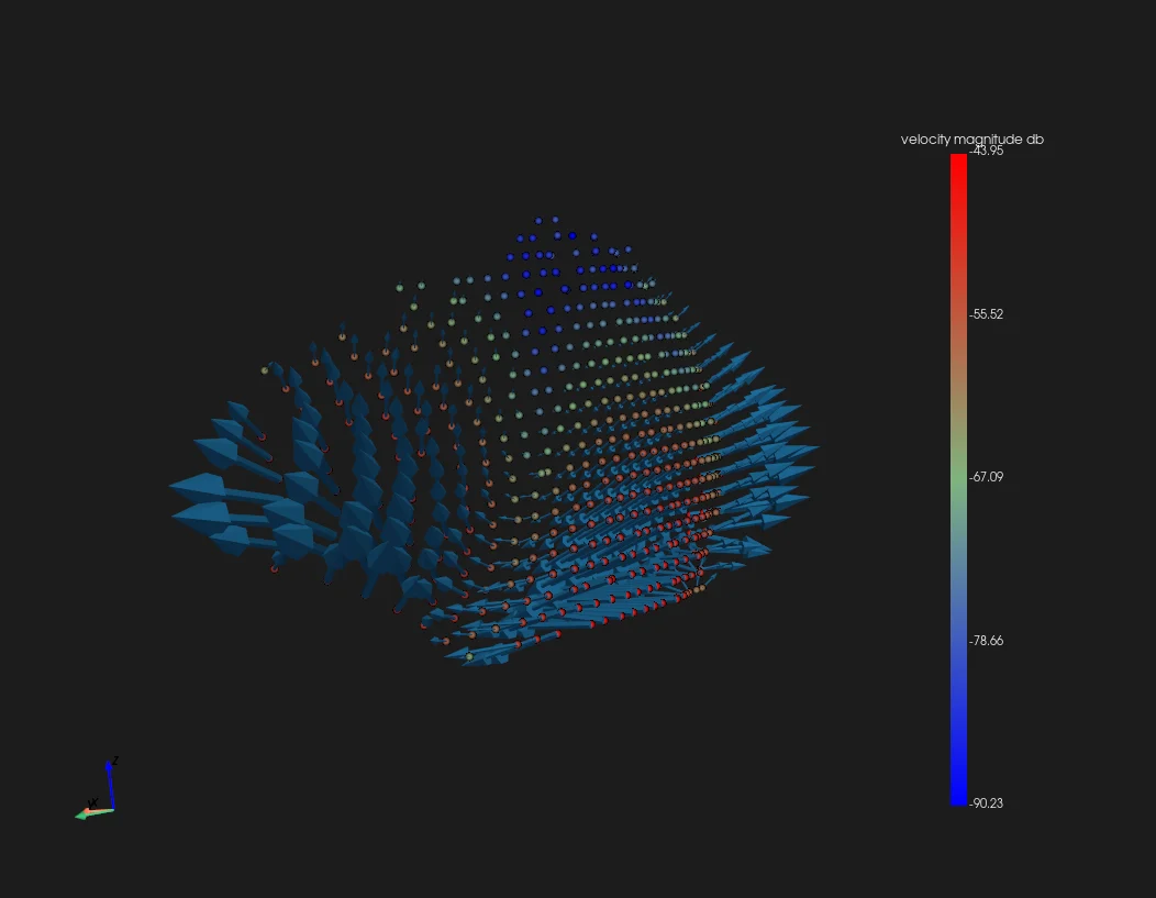
Part 2 follows the reconstruction workflow after acquisition: multiple point clouds are imported and filtered to the region of interest, then spherical fiducials register the scans in a shared coordinate system. The individual line-of-sight measurements are resolved into X, Y and Z velocity components, creating a full-field 3D vibration dataset ready for export to modal-analysis software such as Siemens Testlab.

Key advantages

Simple: One single Q2 recovers a complete 3D velocity field.

  • Compact & affordable: Avoid multi-LDV rigs, robotic arms, and heavy lab integration.
  • Fast: No per-point calibration campaigns; the same instrument provides metrology and vibrometry.
  • Versatile: Deployable in labs, factories, and field sites without dedicated installations.
Full-field 3D velocity vector reconstruction on a curved structure

How it works

Ommatidia Q2 extends Laser Doppler Vibrometry from directional, line-of-sight measurements to full-field 3D velocity vectors—using one single parallel-scanning Laser RADAR. By acquiring multiple Q2 views, registering them via spherical fiducials, and phase-aligning the data, the recovery software estimates the three velocity components at each surface point.

The result is a coherent 3D motion field suitable for FEM correlation, modal analysis, ODS, and strain-ready outputs.

Operational benefits

  1. Per view, Q2 acquires a point cloud, beam directions, and line-of-sight (LoS) velocity at illuminated points.
  2. For each surface point seen from three or more independent directions, the 3D velocity vector is solved from the LoS projections; extra views improve robustness via weighted least squares.
  3. Local quality indicators assess observation count, residuals, and geometric conditioning.
  4. Export allows advanced visualisation and further processing in commercial FEA/engineering software packages.
docx-07-image15
Strain over a sherical shell (µstrain)

Proof points

Plan as a single coordinated campaign, not isolated scans.

  • Use Ommatidia planner tools to evaluate spatial coverage, sampling density, geometric consistency, phase consistency, and repeatable signal quality across views.
  • Generate synthetic datasets to load in the reconstruction tool.
  • Compare agains the ground truth to assess the effect of different experimental protocols, reconstruction algorithms and conditions (sampling, noise, interpolation scheme, etc.).
docx-05-image13

Webinar: 3D Velocity & Strain Workflow

Talk to Ommatidia

Discuss how this measurement approach could support applications workflows with the Ommatidia team.

Ommatidia Upgrade & Trade-In Program

Upgrade to Ommatidia’s latest Laser RADAR technology and unlock more capability for your next measurement challenge. Whether you are expanding an existing setup or replacing an older system, we offer tailored upgrade options with discounts of up to 40%.

If you are currently using another manufacturer’s system, send us your model and measurement requirements. We will review your trade-in possibilities, identify the best Ommatidia configuration, and outline a practical upgrade path for your team.

Discuss your upgrade or trade-in

3D velocity reconstruction questions

How does one Q2 reconstruct a 3D velocity field?

One Q2 is positioned at three or more viewpoints around the same surface region. Each view captures line-of-sight velocity and geometry; registered, phase-aligned measurements then resolve motion into X, Y and Z components.

How are the viewpoints combined?

Each acquisition supplies a point cloud, beam directions and synchronized velocity. Spherical fiducials register the views in one coordinate system, and corresponding surface points are combined through a weighted solution to produce the 3D vector field.

What makes the reconstructed field engineering-ready?

Direction diversity, geometric conditioning, registration quality, phase consistency, signal-to-noise ratio and reconstruction residuals provide a clear quality record for every point. The workflow carries these checks through acquisition, reconstruction and export.

How does the 3D field support strain analysis?

The registered displacement or velocity field feeds spatial-gradient analysis on the selected mesh or neighbourhood. Coordinate alignment, filtering and reference comparison turn the reconstructed vectors into traceable strain-ready maps for model correlation and design assessment.